Patent Office
by Elton Gish
Reprinted from "Crown Jewels of the Wire", October 1992, page 18
NEVIN Y. SINDLINGER
SELF-TYING INSULATOR PATENT
Jack Snyder tracked down Mr. Sindlinger's family in his home town of Toledo,
Ohio way back in 1974 after he saw a copy of the Sindlinger patent drawing on the
cover of the July, 1974 issue of Crown Jewels. Jack interviewed Mr.
Sindlinger's wife and daughter who showed him two pottery models and documentation, and they allowed him to make a couple of
photographs. In the
July, 1984 issue of CJ, Jack published the information from that interview and
the two photographs that he made of the two pottery models. Finally, in 1991,
Jack's dream came true when he purchased the two pottery insulator models from
Mrs. Sindlinger along with the documentation. He very generously mailed
one of the models to me so I could inspect it, make ink drawings, and take a few
photographs. I was amazed at how small the model was as you could easily wrap
your whole hand around it. It is rare indeed that family members of a patentee
remain that can relate some of the facts behind the patent. Thanks to Jack's
efforts, we have a more complete record of the events surrounding this unusual
patent.
Below are the ink drawings that I made. We will not assign a U-number to
this design since only pottery models exist, no commercial production was
ever made, and the original intent was to make them of glass.
Nevin Y. Sindlinger lived in Toledo, Ohio where he worked for the Wheeling
and Lake Erie Railroad as a combination electrician and signalman. Mr.
Sindlinger was well aware of the effort required to secure the signal wire to an
insulator by means of a tie-wire. He thought that there must be an easier way,
and, to that end, he set out to develop an insulator design to make his job
easier by eliminating the need for a tie-wire. Mr. Sindlinger was a constant
tinkerer, so it was natural for him to set out to solve this problem. He sought
the advice of fellow workers and others, and, after two years of
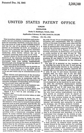
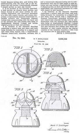
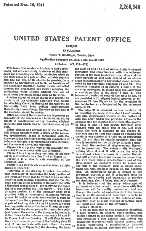
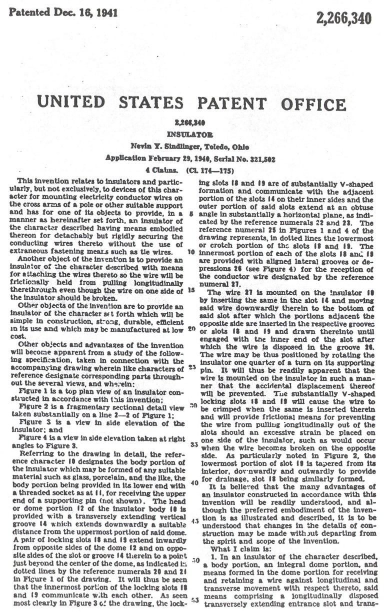
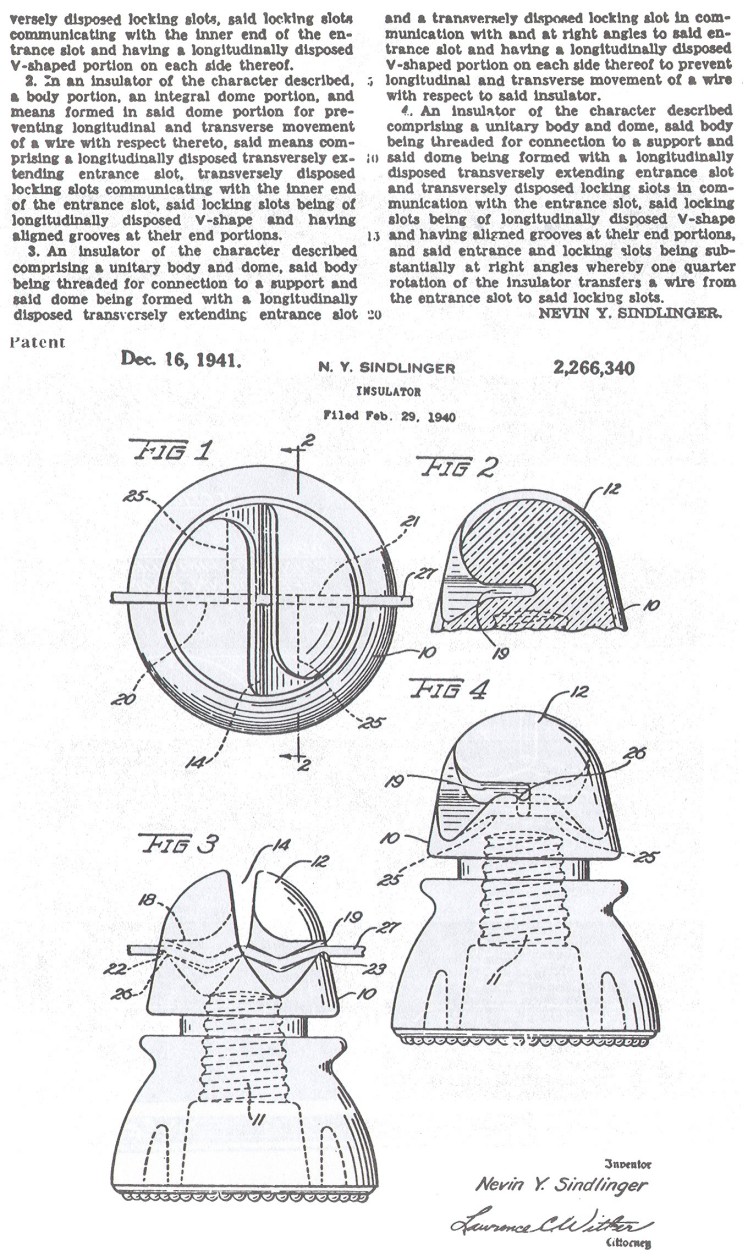
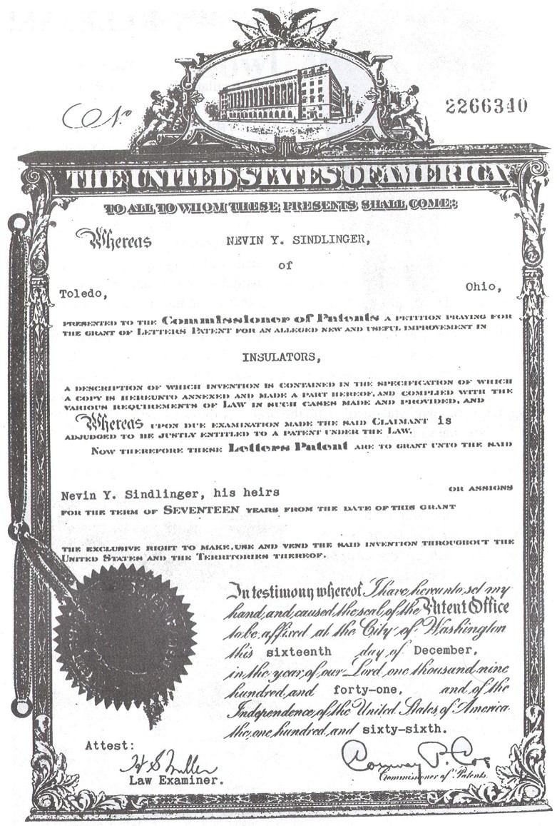
trial-and-error, applied for a patent on February 29, 1940 detailing the design
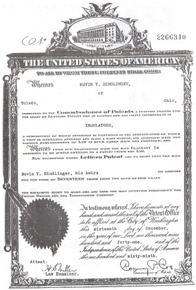
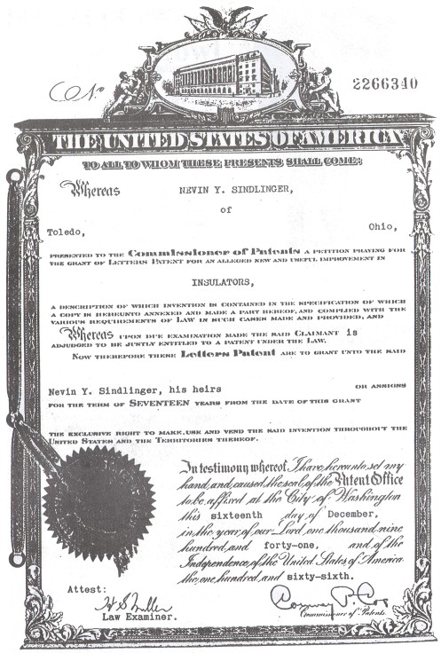
of a self-tying twist lock insulator. Mr. Sindlinger was granted patent
2,266,340 on December 16, 1941. A copy of the patent grant and the patent are at
the end of this article.
Mr. Sindlinger was not the first person to seek a way
to eliminate the need for tie-wires. Indeed, he must have been the last person
to do so since he was granted the last patent for a self-tying insulator. There
have been about 130 patents granted for self-tying designs, but only a handful
were put into production. Many of the self-tying patents are quite unique and
complicated which either required impossible manufacturing techniques, or they
were simply too expensive to produce. It seemed that everyone had an idea for a
"better mousetrap", but few of the patents were practical. The bulk of
the patents for self-tying insulators were granted from 1902 to 1920.
Only
eleven self-tying insulator patents were known to have been produced as
represented by extant specimens:
U-182A/B (Prenzel,1885)
CD 141.8 (Buzby, 1890)
CD 158.9 (Hauty, 1893)
CD 207 (Renault, 1900)
* U-184 & CD 206.5 (Harloe, 1902)
U-181 (Bell,1903)
CD 141.7 (Twiggs, 1905)
* U-185 (Slusser, 1908)
* U-183
(Ranson, 1909)
U-187 (Pierce, 1910) *
U-186(Purkey,1914)
Four of these patents
(marked with "*" above) were either twist-lock styles or the wire was
slightly bent by twisting the insulator back and forth to align the wire with
the projections. The classic example of this later operation is the Harloe
patent.
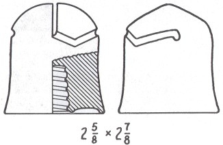
The Sindlinger twist-lock design appears to be stronger and less prone
to breaking than the fragile looking projections found on U-183, U-184 and
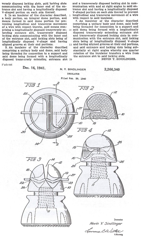
U-185. After first unscrewing the Sindlinger insulator 1/4 turn, the line wire
was then placed in the vertical slot which was formed all the way through the
top of the insulator. Then, by twisting the insulator (screwing it back down on
the pin), the line wire becomes slightly bent by the two downward pointed top
edges halfway along the two lateral grooves. The wire would then be guided
upward by the sloped groove until it fell into the small slot or notch at the
end of each groove. Thus, the line wire was snapped into its final resting and
held securely by the two notches on either side of the insulator, and by the two bent sections of wire. Jack tried this with
a piece of wire and happily reports that the pottery model works perfectly! The
wire actually snapped into the small notch and it was held firmly in place!
I
would guess that the Sindlinger patent was one of the best self-tying designs
since the line wire was slightly bent in two places to firmly secure it against
horizontal movement, and the two deep grooves with a downward notch at the end
would keep the insulator from unscrewing on the pin once the line wire was
snapped into place. However, I doubt that this design could have been mass
produced due to the intricate, deep cuts into the crown.
Mr. Sindlinger's patent
was granted 10 years after the last self-tying patent -- an idea 30 years too
late. In the heyday of self-tying designs, the few styles actually produced met
with very limited success, and they are very uncommon to unique in insulator
collections. So, his idea surely was met with little interest by insulator
manufacturers. His bad timing was further complicated by the fact that the U. S.
was forced into World War II just nine days earlier. Money and material was not
available for investment in anything but the war effort.
Mr. Sindlinger's wife
had second thoughts about her husband spending so much money on a foolish idea.
Upwards of $100 was spent just on patent fees, applications, etc., which was a
sizeable sum in 1940 for most families. Many times that amount was probably
spent on developing the idea, blueprints; patent attorney fees, and making the
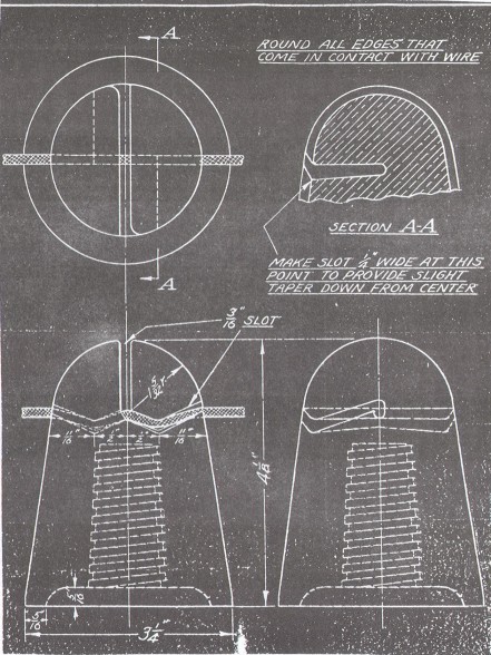
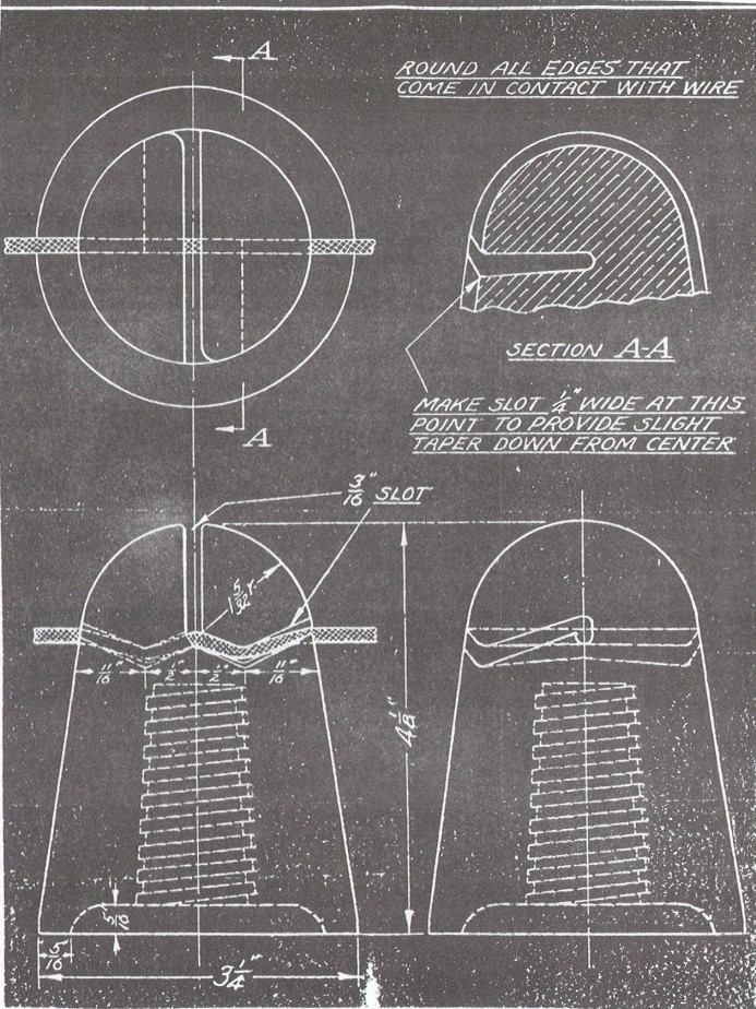
pottery models. Due to lack of money, the two patent models were made by hand in
his workshop. The threaded pin hole is very crude and too small to fit on a
standard pin. He may have used a wooden pin to form the threads, but did not
realize that the clay would shrink after firing. According to Mr. Sindlinger's
daughter, the models had to be fired at an unknown facility in New Philadelphia,
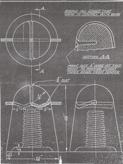
Ohio. Note that the blueprint more closely resembles the pottery models than
does the patent drawing.
The original idea involved a glass insulator. The
patent drawing even resembles a Hemingray CD 208 or CD 213. Mr. Sindlinger
approached Western Electric to see if they would be interested, but they
referred him to Hemingray. Nothing ever came of the correspondence with
Hemingray. The design was probably too costly to produce from glass and
prohibitively complicated, too, for porcelain since costly glazewelding
techniques had not been used for more than 20 years (U-186 required making it in
three separate pieces and fusing them together with glaze). Hemingray 42's could
be turned out by the millions in short order, and labor to add tie-wires was
cheap. All of the years of effort spent developing this idea were wasted. The
two pottery models are all that remain of one man's dream.
Below are six photographs that show all of the details of one or the pottery
models from every conceivable angle.
Medium Image (186 Kb)
Large Image (411 Kb)
Medium Image (132 Kb)
Large Image (296 Kb)
Medium Image (105 Kb)
Large Image (246 Kb)
Medium Image (192 Kb)
Large Image (292 Kb)
| 
)
)
)
)
)
)
)